
Page 75 - Perko
P. 75
U.S.C.G. Electrical Standards & Wiring Diagrams
On January 31, 1977 the U.S.C.G. Published Safety Standards for
Marine Electrical Systems. These Standards Cover Such Technical Details As:
• Batteries and Associated Conductors • Overcurrent Protection
• Conductor Size and Ampacity • Ignition Protection
• Strain Relief and Pull Tests • Grounding
• Termination Requirements • Insulation
A particular electrical component may be affected by some or all of the above categories. Those categories related to product design have
been complied with, however, many additional details must be considered by the installer of the equipment as well in order to achieve
compliance with this standard. It is suggested that the actual standard be familiarized when installing equipment. Perhaps one of
the most critical requirements is ignition protection. A product that is marked “Ignition Protected” can be used in that area of a boat that
is not isolated from a gasoline fuel vapor source. Refer to the actual standard for a determination of what parts of a boat require
Ignition Protected products.
If a product is not plainly marked “Ignition Protected” then assume it is not.
For Details On All Of The Above, Obtain The Following: U.S.C.G. Safety Standards
For Electrical Systems CFR Title 33, Chapter 1, Subchapter S, Part 183, Subpart I
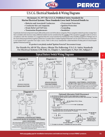
Typical Battery Switch Wiring Diagrams
5
2
2
2
Diagram #1 Diagram #2 Diagram #3
Alternator Alternator Field
Alternator Alternator Field Disconnect
Field
Field Disconnect
Disconnect
Disconnect
SINGLE ENGINE 2 ENGINES, 2 BATTERIES, 2 SWITCHES. Battery Switches and Electrical Components
SINGLE ENGINE TWO BATTERIES This allows either engine to be started by either battery.
Port switch indicates which battery (#1, All, #2) is connected to
SINGLE BATTERY Switch Position indicates which battery the port engine and the starboard switch indicates which
(#1, All, #2) is connected to engine.
battery (#1, All, #2) is connected to starboard engine.
2
Diagram #4
Alternator Field Alternator Field Optional Alternator Field Disconnect
2
Disconnect
Disconnect
2 ENGINES, 2 ENGINE BATTERIES,
1 SEPARATE BANK OF LIGHTING BATTERIES
AND 2 SWITCHES
This allows both engines to be used to charge Lighting Batteries.
Port switch indicates which battery (port only, port lighting only)
is connected to the port engine and the starboard switch
indicates which battery (starboard only, starboard lighting only) is
connected to starboard engine.
Visit www.perko.com for installation instructions and technical drawings on most PERKO products. 75
®